What is thick-walled Injection molding?
Injection molding is a very efficient method of manufacturing complex geometry with great strength to weight ratios. Thick-walled molding tends to break many of the rules for good design of injection molded parts. Traditional part design for molding will specify wall thicknesses from .060” – .180” and specify uniform thickness of wall sections in the part. In traditional injection molding part design thick sections of the part are “cored out”. Coring out is a method of removing plastic from thick sections of the design to maintain wall uniformity, reduce part weight and cycle time. Parts with wall sections at .250” or greater are considered thick-walled parts. Some applications require wall sections to go beyond the general rule to provide the required performance. Texas Injection Molding has considerable experience in designing and molding thick-walled parts.
Why applications would require thick walls?
- Thick walls may be necessary when parts are weight bearing and ribs will buckle under load requiring solid forms.
- Mass is necessary for the design of the part
- In areas of high abrasion thick sections provide a sacrificial barrier
- Plastic is a good insulator of heat and thick sections may be required to meet specific insulation requirements
- In many instances, plastic parts are replacing machined aluminum parts previously used in an application for weight or manufacturing cost reduction. For many reasons, the geometry is fixed in the earlier design and follows thru in the plastic part along with the thick sections.
- May also be used as an alternative to compression molding for cycle-time reduction and increased production capacity.
What manufacturing challenges do thick-walled parts cause?
- Part cost is primarily driven by material cost and cycle time. The greater the wall thickness the more material is required and longer the cycle time to cool the parts. Balancing manufacturing efficiencies and part quality is critical to molding parts with thick wall sections.
- Maintaining tolerances of +/- .002”- .005” that may be typical for most parts become challenging for parts with thicker walls and or longer sections due to the volume of material that is shrinking across the sections during cooling. The affect of variation in the process will be magnified the thicker the wall section.
- When non-uniform wall sections are designed in a part, the thick sections shrink more than the thin sections parts and will cause internal stress or warpage.
- Molded parts cool from the outside in, so when parts solidify on the outside but are continuing to shrink on the inside, they may pull the outside walls in known as “sink marks” or create vacuum voids within the part. Vacuum voids are bubbles or pockets within the section of the part.
What causes vacuum voids in thick walled parts?
As the plastic melt cools it shrinks. When under pack pressure during the cooling process of injection molding, the steel will remove heat from the plastic. The outside surfaces of the part will cool and take the form of the mold cavity. Even though the outside of the part is solid and can be ejected from the cavity, the inside of the thick section will remain soft and continue to cool after the part is ejected. As the plastic shrinks during cooling it will either pull the outer walls in leaving a “sink mark” on the outside of the part or pull a vacuum void on the inside of the part.
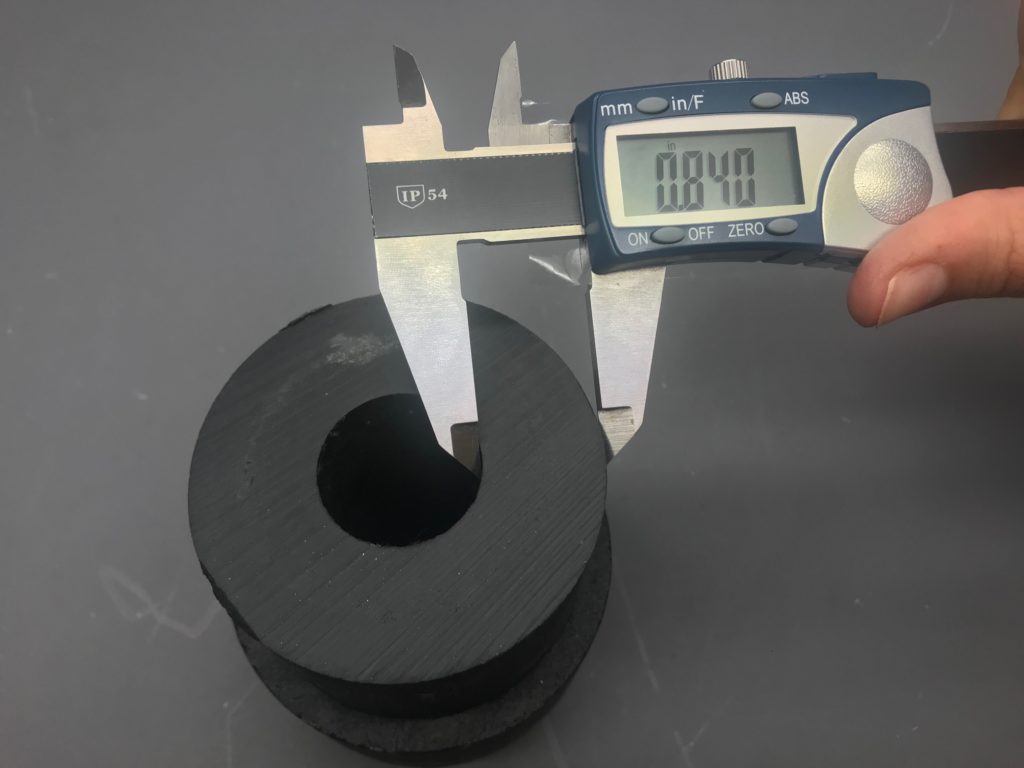
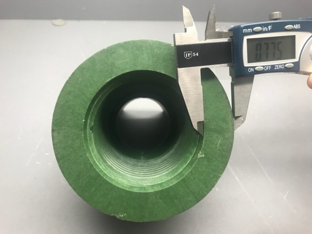
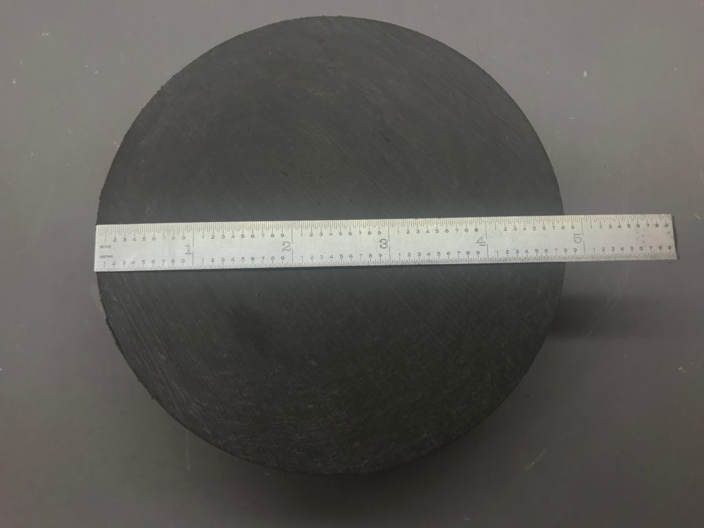
How to inspect for voids?
The most rudimentary method for detecting large voids is by weighing the part and comparing to the standard weight. Mass X Volume. If the molded part is a full shot and weighs less than the standard it is likely that there is a void. You can cut the part across the thick sections to see the voids and adjust the molding process to eliminate. Ultrasonic is a preferred method to detect voids and can detect voids that will not be detected by comparing the weight to the standard. Ultrasonic introduces high frequency sound waves to the part with a small probe called a transducer and generate predictable patterns. Voids will generate an echo which will allow the operator to accurately identify internal voids. X-ray is a better method when identifying voids in small sections. The best method is micro-CT. Micro-CT can resolve a void that is as small as 1/2 the diameter of an individual glass fiber. The biggest issue with these fine resolution methods is the sample size has to be small. (Approximately 1/2″) There is new technology by North Star Imaging that can sample a much larger diameter. (Approximately 20″) Even with the large sample size the technology can resolve a particle or void that is 1/10th the diameter of a carbon fiber. These systems are great for research laboratories, but not practical for large volume production.
How do you eliminate voids?
Voids can be minimized to acceptable levels or eliminated by modifying the processing conditions. The main process variables would include the pack pressure, cooling time and cooling temperature. The challenge for the processor is to find the process that balances maximum efficiency of cycle time while maintaining voids within tolerances.
For assistance in design or manufacturing parts with thick sections, contact us.