Learn what injection molding tolerances are achievable, what affects them, and how to specify them correctly on your molded parts.
Injection molding tolerances define how closely a manufactured part matches the design intent. Tolerances that are too tight add cost and extend qualification time. The chosen material and process may also make them difficult or impossible to maintain consistently.
Tolerances that are too loose can create parts that don’t fit the assembly or perform as designed. Getting tolerances right — and understanding what drives them — is a critical part of injection molding design.
What Is Achievable in Injection Molding
Injection molded part tolerances commonly range from ±0.005 to ±0.010 inch (±0.127 to ±0.254 mm) for relatively small, well-controlled dimensions. Part geometry, feature size, material, tooling, and process capability all influence the final tolerance.
Precision molding can achieve ±0.001–0.002 inch (±0.025–0.050 mm) on selected critical dimensions. Reaching this level requires precision tooling, robust process control, appropriate material selection, and capable measurement systems.
The ranges below provide general guidelines rather than universal tolerance classes. Engineers and molders should evaluate achievable tolerances for each specific part, resin, dimension, mold design, and production process.
- Commercial tolerance ±0.010 inch (±0.254 mm) — a practical target for many non-critical features where appearance and general fit are the primary requirements
- Standard tolerance ±0.005 inch (±0.127 mm) — suitable for many relatively small features when the mold and process maintain good dimensional control
- Fine tolerance ±0.003 inch (±0.076 mm) — requires greater attention to part geometry, gate location, mold temperature, material behavior, tooling, and process consistency
- Precision tolerance ±0.001–0.002 inch (±0.025–0.050 mm) — requires precision tooling, scientific injection molding, process validation, controlled conditions, and capable metrology
Tolerance Design Consideration
Tighter tolerances demand greater control over tooling, material behavior, processing conditions, and measurement. Apply precision tolerances only where assembly or part function genuinely requires them.
What Drives Tolerance in Injection Molding
Material Shrinkage
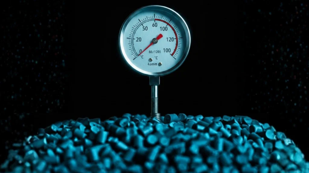
All thermoplastics shrink as they cool from melt temperature to room temperature. Mold designers size the cavity to compensate for the expected material shrinkage.
Shrinkage creates one of the primary sources of dimensional variation in injection molded parts. It does not occur perfectly uniformly or remain completely consistent from shot to shot.
Materials such as PP and many nylon grades have higher or more variable shrinkage. As a result, they generally present greater challenges for tight dimensional control. Lower-shrinkage amorphous materials such as ABS and PC can make tight tolerances easier to maintain.
Amorphous vs. Semi-Crystalline
Amorphous materials such as ABS, PC, PMMA, and PS generally have lower and more predictable shrinkage. Semi-crystalline materials such as PP, nylon, POM, and PET typically shrink more.
For this reason, amorphous materials often make tight dimensional control easier. However, the final capability still depends on the part design, tooling, and molding process.
Glass-filled nylon may offer a strong option when an application requires nylon and tight dimensional control. Glass reinforcement reduces overall shrinkage and moisture-related dimensional change. However, fiber orientation can create anisotropic shrinkage. Gate location and flow direction therefore become especially important.
Gate Location and Flow Path
Shrinkage in the flow direction can differ from shrinkage across the flow direction. This effect becomes especially important with semi-crystalline and fiber-reinforced materials.
Gate location controls how material flows through the mold cavity. That flow pattern influences shrinkage, fiber orientation, and warpage. Engineers should consider these effects when designing tight-tolerance features.
Mold Temperature and Process Consistency
Changes in mold temperature can alter shrinkage from shot to shot and affect finished dimensions. Poor or imbalanced cooling can also create dimensional variation.
Adjusting injection parameters alone may not solve problems caused by poor cooling. Scientific molding helps reduce variation by identifying, documenting, and controlling the process variables that affect part quality.
Feature Type and Location
Molders can often control relationships between features in the same mold half more tightly. Dimensions that cross the parting line introduce additional sources of variation from mold alignment and movement.
Where possible, designers should keep tightly toleranced relationships within a single mold half. They should also consider parting line effects during DFM.
How to Specify Tolerances Correctly
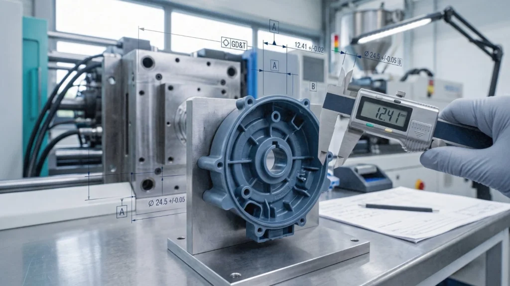
- Use GD&T where appropriate — Geometric Dimensioning and Tolerancing communicates functional design intent more clearly on complex parts. It can also prevent unnecessarily restrictive coordinate tolerances
- Distinguish between critical and non-critical features — apply tight tolerances only where assembly, fit, sealing, motion, or function genuinely requires them. Use broader general tolerances where the design allows
- Keep critical dimensions “steel safe” where possible — moldmakers can adjust steel-safe dimensions after initial sampling by removing steel. This approach generally costs less than adding steel, welding, or rebuilding a mold component
- Account for moisture — nylon and other hygroscopic resins absorb moisture from their environment. Define the material conditioning state for dimensional inspection. Also account for moisture-related dimensional change when it could affect fit or function
- Specify measurement conditions — temperature, humidity, conditioning time, measurement method, and fixture setup can all influence inspection results
Drawing Best Practice
Separate truly critical dimensions from general part tolerances. This tells the toolmaker and molder where the design genuinely requires precision. It also identifies where normal process variation remains acceptable.
Frequently Asked Questions
What is the tightest tolerance achievable in injection molding?
Specialized precision injection molding can achieve tolerances around ±0.001 inch (±0.025 mm) on selected features. However, engineers should not treat this as a universal production capability.
A tolerance around ±0.002 inch (±0.050 mm) represents a more realistic tight-tolerance target for many precision molded features. The material, tooling, process, part geometry, and measurement system must all support the requirement. Manufacturers should establish actual capability for the specific part and process.
Why are injection molding tolerances looser than CNC machining?
CNC machining controls dimensions by removing material with precisely controlled cutting tools. Injection molding must account for polymer shrinkage, cooling, material behavior, mold conditions, and process variation.
Precision CNC machining can hold ±0.001 inch or tighter on suitable features. Achieving comparable tolerances in injection molding requires much greater control over material selection, tooling, processing, and measurement.
How does wall thickness affect dimensional tolerance?
Thicker sections take longer to cool and solidify. This longer cooling time creates more opportunity for differential shrinkage and dimensional variation.
Thick or non-uniform sections can also increase residual stress and warpage. Uniform wall thickness and well-designed transitions generally produce more predictable dimensions.
Related Guides
- DFM for Injection Molding: 12 Design Rules
- Scientific Injection Molding Explained: How Data-Driven Process Control Produces Consistent Parts
- Designing for Injection Molding: The Engineer’s Guide
- 10 Common Injection Molding Defects: What Causes Them and How to Prevent Each One
- Guide to Injection Molding Material Selection