A step-by-step guide to the plastic injection molding process — what happens at each stage and why it matters for part quality.
Injection molding works by melting plastic pellets and injecting the molten material into a precision metal mold under high pressure. Once the plastic cools and solidifies, the mold opens, the part is ejected, and the cycle begins again. That description is accurate — but it leaves out the process decisions that separate a good part from a defective one.
This guide walks through every stage in the cycle with the detail engineers and buyers need to understand what they are buying and what their design choices affect.
Key Process Insight
Injection molding quality depends on more than simply filling a mold with plastic. Clamp force, injection speed, packing pressure, cooling time, mold temperature, gate design, and ejection strategy all influence whether the final part meets dimensional, cosmetic, and mechanical requirements.
The Five Stages of the Injection Molding Cycle

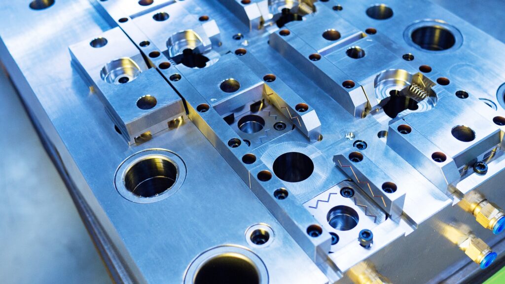
Technician inspecting injection mold tooling to support precision, maintenance, and quality control in plastic part production.
Stage 1 — Mold Clamping
The injection molding cycle begins with the clamping unit pressing the two mold halves together. Clamp force is measured in tons and must exceed the separating force created by injection pressure acting on the projected area of the part. A part with a projected area of 20 square inches being molded at 15,000 psi injection pressure requires a minimum of 150 tons of clamp force just to hold the mold closed. Insufficient clamping causes flash — thin plastic fins at the parting line.
The mold remains clamped for the entire injection, packing, and cooling stages. Only when the part is fully solidified does the clamp retract to allow ejection.
Stage 2 — Plasticizing and Injection
While the previous part cools, the barrel is preparing the next shot. A rotating screw conveys plastic pellets from the hopper through the heated barrel, melting them by a combination of conductive heat from the barrel walls and frictional heat generated by the screw rotation. The screw retracts as molten plastic accumulates in the shot chamber ahead of the screw tip.
When the shot is ready and the previous part has cooled, the screw advances like a plunger, forcing the melt through the nozzle, into the sprue, through the runner system, and past the gate into the mold cavity. Injection speed and pressure are precisely controlled — fill too slowly and the plastic freezes before the cavity is full; fill too fast and you generate excessive shear heat, gas traps, and surface defects.
Stage 3 — Packing and Dwelling
After the cavity fills, the machine transitions from velocity-controlled injection to pressure-controlled packing. Packing pressure pushes additional plastic into the cavity to compensate for volumetric shrinkage as the material cools. Without adequate packing pressure, sink marks appear on surfaces opposite thick walls and ribs. With too much packing pressure, parts stick in the mold and dimensional tolerances go out of spec.
The switchover point from injection to packing — typically based on screw position or cavity pressure — is the most critical process parameter in injection molding. It is where the scientific injection molding approach differs fundamentally from trial and error.
Stage 4 — Cooling
The longest stage of most injection molding cycles is cooling — typically 50 to 80% of total cycle time. The mold is actively cooled through channels machined into the tool, through which temperature-controlled water circulates. Cooling time is determined by wall thickness, material thermal properties, and the required ejection temperature of the specific resin.
Thicker walls require longer cooling times in proportion to the square of the wall thickness — doubling wall thickness quadruples cooling time. This is the thermodynamic reason why uniform wall thickness is the single most important rule in injection molding part design.
Stage 5 — Ejection
Once the part has reached ejection temperature — the temperature at which it is rigid enough to maintain its shape under ejector pin force — the mold opens and ejector pins push the part out of the cavity half. The ejector plate advances, the pins contact the part, and the part releases and falls onto a conveyor or into a bin.
Ejector pin placement is a design decision, not an afterthought. Pins leave witness marks, which are small circular impressions on the part surface wherever they contact. They must push on surfaces that can handle the load without deforming, and they must be placed to eject the part straight, without rocking or tipping that would drag the part across cavity surfaces.
What Controls Part Quality
The quality of an injection molded part is determined by three interacting systems: the part design, the mold design, and the process. A good part design that ignores moldability will generate problems that no amount of process optimization can fix. A good process running a poorly designed mold produces inconsistent results.
The relationship between all three is why experienced engineers and molders involve the molder early — before the mold is cut.
| Quality Control Factor | What It Affects |
|---|---|
| Part design | Wall thickness, draft angles, rib geometry, gate location, and feature tolerances all determine what the process must do to produce a good part. |
| Mold design | Gate type, runner layout, cooling channel placement, vent location, and ejector system design determine how consistently the mold fills, cools, and releases. |
| Process | Melt temperature, injection speed, packing pressure, cooling time, and mold temperature are tuned to the specific material and tool to achieve repeatable dimensions and surface quality. |
Design Note
Injection molding problems are rarely caused by one variable in isolation. Part geometry, tool design, resin behavior, and machine settings all interact, which is why early design-for-manufacturability review is critical before tooling begins.
Frequently Asked Questions
How long does one injection molding cycle take?
Most production injection molding cycles run between 15 and 90 seconds. Thin-wall packaging parts can cycle in under 5 seconds. Thick, complex structural parts may take 3–5 minutes. Cycle time is dominated by cooling time, which is proportional to the square of the wall thickness.
What is the screw doing during the injection molding cycle?
During cooling of the previous shot, the screw rotates to melt and convey plastic, retracting to accumulate the next shot in the barrel. During injection, the screw stops rotating and advances like a plunger to push the melt into the mold. During packing, the screw holds pressure. During cooling, it retracts again to prepare the next shot — so plasticizing happens in parallel with part cooling.
What causes defects in injection molding?
Most defects originate from one of three sources: design, tooling, or process. Design-related defects can come from inadequate draft, uneven wall thickness, or poor gate location. Tooling-related defects can come from poor venting, unbalanced cooling, or incorrect gate size. Process-related defects can come from incorrect melt temperature, injection speed, or packing pressure. Identifying the root cause requires separating these three sources — which is what a scientific molding approach does systematically.